MRF6S19200HR3 MRF6S19200HSR3
1
RF Device Data
Freescale Semiconductor
RF Power Field Effect Transistors
N-Channel Enhancement-Mode Lateral MOSFETs
Designed for CDMA base station applications with frequencies from 1930 to
1990 MHz. Suitable for CDMA and multicarrier amplifier applications. To be
used in Class AB and Class C for PCN-PCS/cellular radio applications.
?
Typical Single-Carrier W-CDMA Performance: VDD
= 28 Volts, I
DQ
=
1600 mA, Pout
= 56 Watts Avg., Full Frequency Band, 3GPP Test Model 1,
64 DPCH with 50% Clipping, Channel Bandwidth = 3.84 MHz, Input Signal
PAR = 7.5 dB @ 0.01% Probability on CCDF.
Power Gain ? 17.9 dB
Drain Efficiency ? 29.5%
Device Output Signal PAR ? 5.9 dB @ 0.01% Probability on CCDF
ACPR @ 5 MHz Offset ? -36 dBc in 3.84 MHz Channel Bandwidth
?
Capable of Handling 10:1 VSWR, @ 32 Vdc, 1960 MHz, 130 Watts CW
Output Power
Features
?
100% PAR Tested for Guaranteed Output Power Capability
?
Characterized with Series Equivalent Large-Signal Impedance Parameters
?
Internally Matched for Ease of Use
?
Integrated ESD Protection
?
Greater Negative Gate-Source Voltage Range for Improved Class C
Operation
?
Optimized for Doherty Applications
?
RoHS Compliant
?
In Tape and Reel. R3 Suffix = 250 Units per 56 mm, 13 inch Reel.
Table 1. Maximum Ratings
Rating
Symbol
Value
Unit
Drain-Source Voltage
VDSS
-0.5, +66
Vdc
Gate-Source Voltage
VGS
-6.0, +10
Vdc
Operating Voltage
VDD
32, +0
Vdc
Storage Temperature Range
Tstg
- 65 to +150
°C
Case Operating Temperature
TC
150
°C
Operating Junction Temperature (1,2)
TJ
225
°C
CW Operation @ TC
= 25
°C
Derate above 25°C
CW
130
0.49
W
W/°C
Table 2. Thermal Characteristics
Characteristic
Symbol
Value (2,3)
Unit
Thermal Resistance, Junction to Case
Case Temperature 110°C, 89 W CW
Case Temperature 100°C, 55 W CW
RθJC
0.35
0.36
°C/W
1. Continuous use at maximum temperature will affect MTTF.
2. MTTF calculator available at http://www.freescale.com/rf. Select Software & Tools/Development Tools/Calculators to access
MTTF calculators by product.
3. Refer to AN1955, Thermal Measurement Methodology of RF Power Amplifiers. Go to http://www.freescale.com/rf.
Select Documentation/Application Notes - AN1955.
Document Number: MRF6S19200H
Rev. 0, 3/2008
Freescale Semiconductor
Technical Data
MRF6S19200HR3
MRF6S19200HSR3
1930-1990 MHz, 56 W AVG., 28 V
SINGLE W-CDMA
LATERAL N-CHANNEL
RF POWER MOSFETs
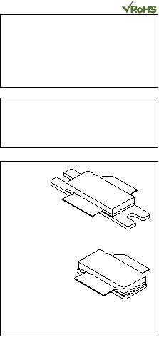
CASE 465A-06, STYLE 1
NI-780S
MRF6S19200HSR3
CASE 465-06, STYLE 1
NI-780
MRF6S19200HR3
?
Freescale Semiconductor, Inc., 2008. All rights reserved.


发布紧急采购,3分钟左右您将得到回复。
相关PDF资料
MRF6S20010GNR1
MOSFT RF N-CH 28V 10W TO270-2 GW
MRF6S21050LSR5
MOSFET RF N-CH 28V 11.5W NI-400S
MRF6S21060NR1
MOSFET RF N-CH 28V 14W TO270-4
MRF6S21100HSR5
MOSFET RF N-CHAN 28V 23W NI-780S
MRF6S21100NR1
MOSFET RF N-CH 28V 23W TO270-4
MRF6S21140HSR5
MOSFET RF N-CHAN 28V 30W NI-880S
MRF6S21190HSR5
MOSFET RF N-CH 54W NI880S
MRF6S23100HSR5
MOSFET RF N-CHAN 28V 20W NI-780S
相关代理商/技术参数
MRF6S20010GNR1
功能描述:射频MOSFET电源晶体管 HV6 2GHZ 10W RoHS:否 制造商:Freescale Semiconductor 配置:Single 晶体管极性: 频率:1800 MHz to 2000 MHz 增益:27 dB 输出功率:100 W 汲极/源极击穿电压: 漏极连续电流: 闸/源击穿电压: 最大工作温度: 封装 / 箱体:NI-780-4 封装:Tray
MRF6S20010GNR1-CUT TAPE
制造商:Freescale 功能描述:MRF6S20010 Series 1.6 to 2.2 GHz 28 V 10 W RF Power N-Ch Mosfet - TO-270
MRF6S20010NR1
功能描述:射频MOSFET电源晶体管 HV6 2GHZ 10W TO270-2 RoHS:否 制造商:Freescale Semiconductor 配置:Single 晶体管极性: 频率:1800 MHz to 2000 MHz 增益:27 dB 输出功率:100 W 汲极/源极击穿电压: 漏极连续电流: 闸/源击穿电压: 最大工作温度: 封装 / 箱体:NI-780-4 封装:Tray
MRF6S20010NR1_09
制造商:FREESCALE 制造商全称:Freescale Semiconductor, Inc 功能描述:RF Power Field Effect Transistors N-Channel Enhancement-Mode Lateral MOSFETs
MRF6S21050LR3
功能描述:射频MOSFET电源晶体管 HV6 W-CDMA 11.5W NI400L RoHS:否 制造商:Freescale Semiconductor 配置:Single 晶体管极性: 频率:1800 MHz to 2000 MHz 增益:27 dB 输出功率:100 W 汲极/源极击穿电压: 漏极连续电流: 闸/源击穿电压: 最大工作温度: 封装 / 箱体:NI-780-4 封装:Tray
MRF6S21050LR3_08
制造商:FREESCALE 制造商全称:Freescale Semiconductor, Inc 功能描述:RF Power Field Effect Transistors N-Channel Enhancement-Mode Lateral MOSFETs
MRF6S21050LR5
功能描述:射频MOSFET电源晶体管 HV6 W-CDMA 11.5W NI400L RoHS:否 制造商:Freescale Semiconductor 配置:Single 晶体管极性: 频率:1800 MHz to 2000 MHz 增益:27 dB 输出功率:100 W 汲极/源极击穿电压: 漏极连续电流: 闸/源击穿电压: 最大工作温度: 封装 / 箱体:NI-780-4 封装:Tray
MRF6S21050LS
制造商:Freescale Semiconductor 功能描述:
